
Home Photos Articles Ads Documents
Brochure
Owners Manual
The control functions of the Jim Kelley Amplifier have been carefully designed ‘by ear’, with the help of seasoned Rock ‘n’ Roll and Jazz guitar players to provide the widest possible range of usable tones. I say “usable”, because the process of designing good sounds into an amp requires the elimination of all the bad sounds. I prefer to use Active Shelving Equalizer circuits for tone controls instead of the resonant Graphic Equalizer circuits. Although graphic EQ’s can add to the theoretical versatility of an amp, in practice they actually only add to the number of unusable tones. The high-Q, narrow-bandwidth, resonant nature of their design adds an unalterable nasal characteristic to the sound, alters the natural harmonic balance of your instrument.
Another control you will not find on a Jim Kelley Amplifier is a “Master Volume”, in the traditional sense. This type of control originated as a modification to amps whose power output was too great to overdrive at reasonable volume. The Master volume or “clipper” control was devised as a means of providing distortion at a preset volume. In order to develop the distortion, additional gain must be generated in the preamp. The input waveform is then amplified to the point where it becomes clipped on one side. However, the harmonics produced by a class A 12AX7 amplifier circuit are quite different than those generated by power pentodes in a push-pull output circuit. Excessive noise and microphonic problems are also associated with high preamp gain.
The Jim Kelley Amplifier is designed so that the preamp processes equalization and gain, and the power amp can be overdriven to produce harmonic distortion. Each circuit is allowed to do only what it does best. This results in lower noise, wider tonal range, smoother overdrive and cleaner rhythm tones.
The Gain control(s) on your amp should be thought of as overdrive controls – not just volume controls. The Gain control is used to add harmonic sustain, richness and depth to the overdrive at higher settings for solos, or as a limiter control to keep the amp from distorting at lower settings for chords.
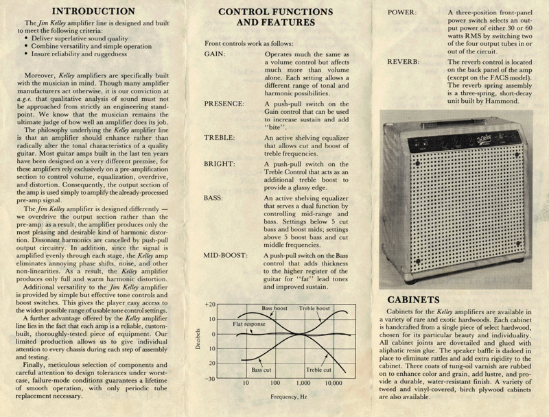
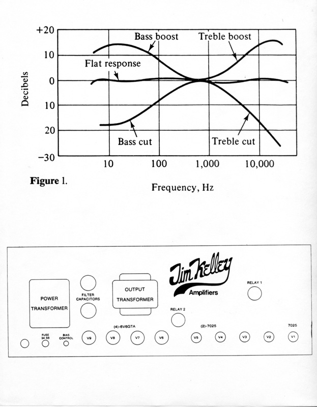
The Treble control is an ‘Active Shelving Equalizer’ that provides cut and boost of treble frequencies. At setting “5”, treble response is basically flat. See Figure 1.
The Bass control is particularly useful. It is also an ‘Active Shelving Equalizer’ and provides cut and boost of bass frequencies. But that’s not all! It may be useful to think of this control as a balance control between bass and mid-range. Settings above “5” boost bass and cut mids, giving the amp a sort of hollowed-out sound. This is good at low gain settings for rhythm comping or acoustic guitar. At higher gain settings in the overdriven mode, the boost region of the Bass control gives the amp sort of an English amp sound. However, too much bass boost at high gain settings may cause the low end to lose clarity.
Settings below “5” cut the bass and boost the mid-range. This range of the control is ideal for soloing at high gain settings. With the bass attenuated and the mids boosted, the high register of the guitar is thicker and the low register is crisper.
In order to emphasize these characteristics even more, the mid-boosts switch (located on the bass control) can be pulled out. This functions essentially as a “fat” switch to increase sustain and add body to the upper register for solos.
The actual change in frequency response when engaging the mid-boost switch can be seen in Fig. 1. Imagine lifting the entire bass-cut/treble-cut visualized by moving the bass-cut/treble-boost curve up 18dB.
This boost is accomplished electronically by switching in a 470pf bypass capacitor around the Gain control, so that at low gain settings the amount of boost is dramatic. However, at higher gain settings the effect is less noticeable.
The Presence boost switch is located on the gain control of the single-channel amps, and on the Gain II control of the FACS amps. Presence controls or presence boost circuits in guitar amps are traditionally wired into the feedback loop and phase-inverter or pre-driver circuits, not in the preamp. The same is true of Jim Kelley Amplifiers. As a result, on the FACS amps the presence boost will affect both channels. The way in which presence boost affects frequency response can be seen in Fig. 1, by raising the entire bass-cut/treble-flat curve by 18dB.
The Reverb control is fairly self-explanatory. On the single-channel amp, the control is located on the back panel. The FACS amp has two Reverb controls, and both are located on the front panel.
Every Jim Kelley Amplifier is equipped with a Hammond-Accutronics type S six-spring, short-decay reverb tank. The tank has been mechanically insulated from the cabinet by means of a double-walled cardboard insulation pad, adhesive foam damping strips and a vinyl liner bag. The system is designed to prevent the feedback that can occur at high levels between the reverb tank and the speaker.
Two loudspeaker jacks are located on the back panel. It is important for the amp to always operate into the correct load impedance. To allow interfacing with a variety of speaker loads, a specially-built output transformer with a tapped secondary is used. The jack on the left is marked “8 ohms” and the jack on the right is marked “4 ohms”. These are the optimum load impedances for each of the two jacks in the 60 watt RMS power position. In the 30 watt RMS position, two of the output tubes are removed from the circuit and the optimum load of each of the jacks changes to 16 ohms and 8 ohms, respectively.
When using the power attenuator, determine the total impedance for the speaker(s) you are using. Then plug speaker(s) into the appropriate jack(s) on the attenuator. Plug the attenuator into the back of the amp using the correct jack for the total speaker impedance and power setting as outlined in the next section.
The optimum load impedance of an amplifier is the one into which the maximum possible amount of power may be transferred. If an amp is not loaded to its optimum impedance, the result is a slight loss of power. The lost power is absorbed as heat by the output transformer and output tubes. The output transformer in the Jim Kelley amplifier is designed to dissipate an amount of heat equal to that generated by a 135 watt amp – more than twice its rated output. This factor allows the amp to be worked into a wider range of load impedances without damaging the transformer or other circuit elements.
Jim Kelley Amplifiers are designed to work well in conjunction with a power attenuator. The power attenuator can be thought of as the ultimate “Master Volume”. It connects between the output of the amp and the speaker as follows:
1. Connect an 18-gauge (or larger) speaker cord from the appropriate loudspeaker jack (8-ohm jack for an 8-ohm speaker, etc.) on the back panel of the amplifier to the jack on the attenuator marked “Amp”.
2. Connect the speaker(s) to the jack on the attenuator marked “Speaker”.
3. The attenuators supplied with Jim Kelley Amplifiers are fitted with a 4-pin Switchcraft jack marked “Footswitch”. This jack must connect with either an external footswitch or to the corresponding jack on the FACS model amps.
The power attenuator manufactured by A.G.E. is a continuously variable L-Pad. It is designed to keep the correct load impedance on the output of the amplifier at all times. It also absorbs the unused power (up to 100 watts) which it then dissipates in the form of heat. Only the amount of power necessary to achieve the desired volume is transferred to the speaker. This allows the amp to be overdriven normally – as it would be at high volumes – in order to generate the best overtone series.
When the attenuator is connected to the internal switching of the standard FACS model amplifier, Channel 1 will be attenuated. Channel 1 can in this way be used as the lead channel. When the amp is switched to Channel 2, the attenuator is bypassed, allowing the amp’s full out power to reach the speaker. This channel can be used for clean rhythm playing.
One additional note about the FACS amp: the push-pull switch on the Gain pot functions as a manual channel switching control. Pull the switch out to use Channel 1, and push it in for Channel 2. (Note: on the FACS Line Amp, the channels are reversed. See “Line Amp Operating Instructions”.)
A footswitch and footswitch jack are provided for remote channel switching. When using the footswitch, make sure the manual channel switching control panel is pushed in; otherwise, the footswitch will not work.
Stand-By Switch
A Stand-By switch is provided on the back panel so that the tubes may be properly warmed up before high voltage is applied to the plates. This increases the life of the tubes. Thirty seconds is usually plenty of time for the filaments to warm up before putting the tubes to work.
It is also recommended to put the amp on stand-by before turning it off. This allows the power supply to discharge before removing the grid bias and filament voltage, thus improving the longevity of the power tubes.
Power Switch
The Power selector is a three-position DPDT switch. The center position is Off, left position is 30 watts RMS and right position is 60 watts RMS. In the 30-watt position, the two middle 6V6GTA output tubes are being used. When the switch is thrown to the 60-watt position, the two outside 6V6GTA’s are also kicked into the circuit.
Ground Switch
This switch is also a three-position type. Its purpose is to help eliminate the shocks, hums and buzzes that may occur when the amp is not grounded. Whenever possible, you should always try to use three-prong AC cords and extension cords with guitar amps and PA equipment. If the building is not able to accommodate three-prong AC plugs, you may still ground your equipment. The commonly used three-to-two prong adaptors are usually supplied with either a ground terminal or lead wire. This is designed so that it may be connected to the screw that holds the faceplate onto the AC outlet. Although it’s not as convenient, this method works as well as the conventional method. [Note: seems incomplete to me]
If you are using two or more amps or other AC-powered devices, ground loop problems may be encountered. A ground loop is created when two or more devices are connected together in a signal path, and also share a common ground at the AC outlet. The result is usually a loud hum. The problem can be remedied by lifting the grounds on all devices except one usually one of the amps) by means of a three-to-two adaptor. Be prepared for some trial and error work. Most importantly, proper grounding prevents shocks.
Effects Loop (Optional)
The Effects Loop available on Jim Kelley Amplifiers is the best on the market. It utilizes separate impedance matching transformers for effects and return. I have found that this is by far the most efficient way of interfacing the high-impedance, high-level tube pre-amp with most state-of-the-art pre-amp level or line-level effects. Problems such as loading, high-end loss, distortion and noise typically associated with effects loops have been eliminated.
Effects loops for the FACS amps are available in four configurations:
1. Master Effects Loop – both channels (two transformers)
2. Effects Loop, lead channel only (two transformers)
3. Effects Loop, rhythm channel only (two transformers)
4. Dual Effects Loop – separate loop for each channel (three transformers)
Speaker Installation
To install a speaker, lay the amplifier on its back and loosen the four screws on the grill so that it may be removed. Install T-nuts into the four holes from the ‘rear’ of the baffle, and load the speaker from the front. It may be necessary to place a gasket behind the speaker frame at the point where it contacts the baffle, and load the speaker from the front. It may be necessary to place a gasket behind the speaker frame at the point where it contacts the baffle. This is to prevent air leakage and rattles. Use four #10-32 X 1” screws to secure speaker in place.
Next, connect the speaker cord. Make sure the grounded side of the cord is connected to the black or unmarked speaker terminal, and the wire connected to the tip of the plug is attached to the red speaker terminal.
Correct speaker phasing is very important, particularly in a multiple speaker system. Out-of-phase speakers can affect the sound quality in two ways:
1. In a multiple-speaker system, bass response is severely attenuated when speakers are not in phase with each other. The speakers must push and pull together as a unit. If they do not, cancellation of the sound wave at low frequencies occurs.
2. In a self-contained amp, speaker phase can have an audible effect at high power levels, even if the amp contains only one speaker. This is because of the fluctuating high-intensity magnetic field set up by the voice coil and its effect on electron flow within the tubes. Speaker phasing determines whether this external field acts as positive feedback or negative feedback and in this way, affects sound quality.
The ribbed side of the sixteen-gauge speaker cord supplied with the Jim Kelley Amplifier connects to ground and should be attached to the black or unmarked speaker terminal. When in doubt, check it with an ohmmeter.
New Amplifier Inspection
When unpacking the amplifier for the first time, inspect the cabinet for possible damaged sustained during shipment. Look for broken dovetail joints, torn vinyl and dented corners or faceplates. If damage has occurred, report it immediately to the freight company or place of purchase. All shipments are covered by insurance.
A brief inspection of the back of the amplifier should be made before using. Check to make sure all tubes and relays are plugged in. There should be no empty sockets. Also, be sure the reverb tank wires are plugged in and that the speaker and attenuators are properly connected.
Tighten chassis mount screws and handle cap screws on top of the cabinet with a Phillips screwdriver. The wood may have compressed slightly during shipment, causing screws to loosen a bit.
Routine Maintenance
The Jim Kelley Amplifier is designed to be relatively maintenance-free. However, some periodic care can add to the life of your amplifier and the enjoyment of your playing. This care falls into two categories:
1. Tube replacement and biasing
2. Care of the cabinet.
Tube Replacement
Proper selection of tubes, both 6V6’s and 12AX7’s is very important in achieving the desired sound from any amplifier. Just as with guitar strings, tubes from different manufacturers sound different. This difference gives the player the opportunity to customize the sound of his or her amplifier simply by selecting the brand of tubes he/she likes best among the brands available.
The low level, high gain 12AX7 stages have the most effect on frequency responses and noise. The 6V6GTA output tubes may be changed to provide different colorations of harmonic distortion. I recommend Groove Tubes for overall performance and longevity. Life expectancy for a quartet of 6V6GTA tubes used 4 or 5 hours a night, 5 nights a week is almost two years. Beyond that point, one should expect a gradual decrease in power and a loss of clarity and reliability.
Should you elect to replace your own tubes, please read and follow this procedure (courtesy of Groove Tubes):
1. Turn off amp and unplug amp from AC outlet. Allow tubes to cool before replacing.
2. Follow tube location guide for correct placement of various models of tubes.
3. When changing power tubes (the big ones), grasp the top of the bottle and slowly work the tube out of its socket using a gentle circular motion. Replace with the new tube, again holding the top of the bottle and using a circular motion. The black plastic nipple in the center of the tube base is slotted to assure correct placement into the socket. Be sure you have the tube in its correct position before further inserting it into the socket. Never force it – it will break if not correctly aligned.
4. When changing pre-amp tubes (the little ones), use the same circular motion described above for both removal and replacement. Notice the large gap between two of the pins and be sure this corresponds to the gap in the socket. This larger gap is usually indicated by a notch or tab on the rim of the socket’s collar. The pins on these tubes can be easily bent when forced. If this occurs, use the front half of a ball point pen to gently rebend it at the glass base. Do not use your fingers, as this will likely break the glass base.
Grid Bias
When replacing output tubes, negative grid bias voltage setting should be checked and if necessary adjusted. The grid bias pot is located on the underside of the chassis next to the fuseholder. Do not attempt this adjustment yourself unless you are equipped with a metered variac or AC ammeter and oscilloscope, and have read the grid bias adjustment procedure.
The bias control on an amp is much like the idle adjustment on an automobile engine. That is, there is an optimum point of bias for an amplifier that will allow for good sound and longer tube life. This optimum point of bias can change every time you change your power tubes, since the efficiency of power tubes will vary from one set to another. Groove Tubes power sets are balance-matched to each other, so that when the bias is set, it is correct for all four tubes. It should be mentioned that all Groove Tubes matched sets are “gain rated” on a one to ten scale.
Troubleshooting tips and the External Component Function Chart can be found on the following pages.
TROUBLESHOOTING
Problem Probable Cause
Amp will not turn on Blown fuse, bad power switch or
AC cord
Blows fuse after warmup Shorted output tubes, amp under-
biased, speaker or attenuator not
properly connected
Blows fuse immediately Shorted filter capacitor,
transformer or rectifier.
Ringing tone or high-frequency Microphonic tube:
oscillation:
· with Gain Control up V1 or V2 (12AX7/7025)
· with Gain Control down V4 (12AX7/7025)
Ringing tone in Reverb V4 Microphonic or Reverb Tank
Microphonic
Intermittent or inconsistent sound, Channel switching relay, bad
or crackling sound while playing speaker or attenuator connection
Intermittent background noise Bad tubes, dirty circuit boards, pots
or sockets
One channel is dead Power attenuator connection, V1
(12AX7), V2 (12AX7) or relay
Won’t switch channels Relay bad or not seated properly
Relay power supply, footswitch,
Gain I switch pulled out
No Reverb Bad Reverb cables, reverb tank,
· both channels out: V3 (12AX7), V4 (12AT7) or relay
· one channel out: Relay
External Component Function Chart
V1 - 12AX7A/7025 Pre-amp I, Lead Channel
V2 - 12AX7A/7025 Pre-amp II, Rhythm Channel
V3 - 12AT7 Reverb Drive
V4 - 12AX7A/7025 Reverb recovery amp and mixer amp (both
channels)
V5 - 12ZX7A/7025 Phase Inverter/Driver
V6-V9 - 6V6GTA Output or Power Tubes
Relay 1 - Pre-Amp and Reverb control switching (not on later models)
Relay 2 - Power attenuator switching
Bias Control - See Text
Fuse Holder - 3 Amp Slo-Blo
C1 – C2 - Power Supply Filter Capacitors (these do not plug in!)
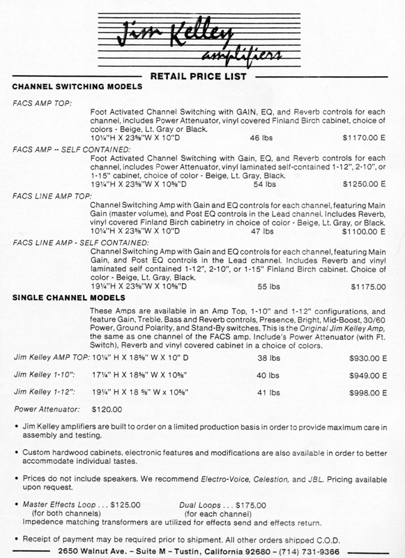
1985 Price List
Contact: jimkelleyamps@gmail.com
256